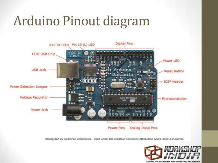

Here the boot loader can also be avoided & the microcontroller program can be done using the header of in-circuit serial programming or ICSP with an Arduino ISP. The communication of this can be done with the STK500 protocol.
#Arduino pinout code
This boot loader lets to upload new code without using an exterior hardware programmer. Microcontroller ATmega328 over the Nano board comes with preprogrammed with a boot loader.

Click the Tools option and select the nano board. The programming of an Arduino nano can be done using the Arduino software. The microcontroller also supports SPI & I2C (TWI) communication. The library-like SoftwareSerial allows serial communication on any of the digital pins on the board. The TX & RX LEDs on the Nano board will blink whenever information is being sent out through the FTDI & USB link in the direction of the computer.
#Arduino pinout software
The Arduino software comprises of a serial monitor to allow easy textual information to transmit and receive from the board. This can be accessible at digital pins like TX, and RX.

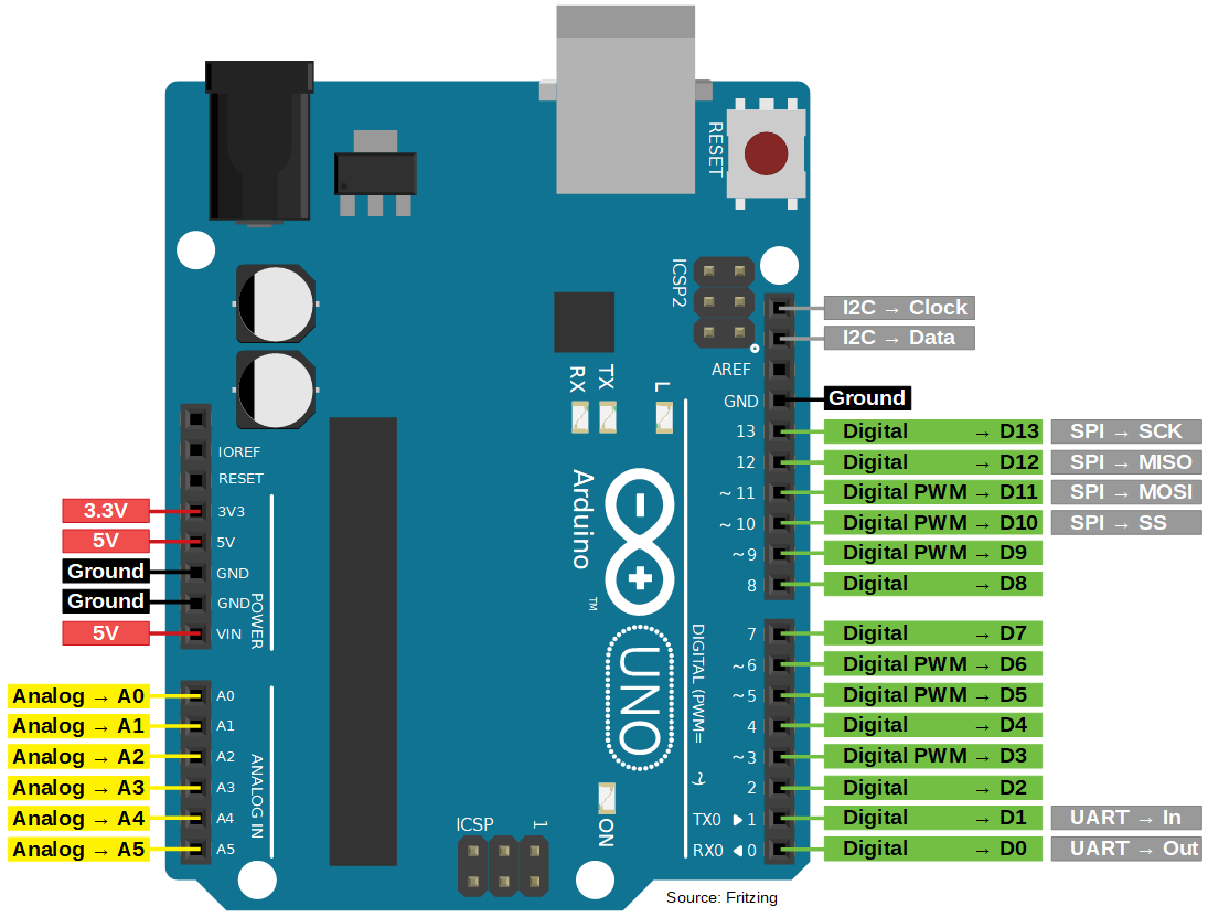
The microcontroller using in Nano board (ATmega328) offers serial communication (UART TTL). The communication of an Arduino Nano board can be done using different sources like using an additional Arduino board, a computer, otherwise using microcontrollers. difference-between-Arduino-UNO-and-Arduino-nano Arduino Nano Communication The main differences between these two are listed in the following table. The programming of UNO can be done with a USB cable whereas Nano uses the mini USB cable. So Uno boards use more space on the system. Because Arduino Uno size is double to nano board. The main difference between these two is the size. The Arduino Nano board is similar to an Arduino UNO board including similar microcontroller like Atmega328p. IIC (A4, A5): These pins are used for supporting TWI communication.ĪREF: This pin is used to give reference voltage to the input voltage Difference between Arduino UNO and Arduino Nano Inbuilt LED (13): This pin is used to activate the LED. SPI (10, 11, 12, & 13): These pins are used for supporting SPI communication. I/O Pins (Digital Pins from D0 – D13): These pins are used as an i/p otherwise o/p pins. RST Pin( Reset): This pin is used to reset the microcontrollerĪnalog Pins (A0-A7): These pins are used to calculate the analog voltage of the board within the range of 0V to 5V 3.3V is the minimum voltage which is generated from the voltage regulator on the board.5V is the regulated power supply voltage of the nano board and it is used to give the supply to the board as well as components.Vin is the input voltage of the board, and it is used when an external power source is used from 7V to 12V.Power Pin (Vin, 3.3V, 5V, GND): These pins are power pins Supports three communications like SPI, IIC, & USARTĪrduino nano pin configuration is shown below and each pin functionality is discussed below.Size of the printed circuit board is 18 X 45mm.ATmega328P Microcontroller is from 8-bit AVR family.The features of an Arduino nano mainly include the following.


 0 kommentar(er)
